


Technical Information
Backfilling Around Pipes and Culverts with Flowable Fill
Compressive Strength
Flowable fill, or controlled Low Strength Concrete, is gaining greater acceptance and use as a backfill material, particularly for work around pipes and culverts. Flowable fill easily enters difficult access areas, provides a relatively uniform compaction density, is self-leveling, and requires minimal crew and equipment for application. With these attributes, plus the ability to control its strength in cases requiring either re-excavation (lower strengths) or heavy surface loads (higher strengths), flowable fill is the solution being recommended by concrete producers for private and public service projects.
 There are two important considerations when using flowable fill around underground pipes or culverts. First, planners must determine if the pipe or culvert can support the weight of the flowable fill during placement. Consult with the pipe's manufacturer or a structural engineer to confirm its capacity using a unit weight of flowable fill, 7f, equal to 125 lb per cubic feet (pcf). Second, the rate or staging of the pours must be determined to prevent the floatation of the pipe.
A determination of the maximum depth of a pour of flowable fill around an underground facility is important to avoid the case where the pipe or culvert could become buoyant. A pipe that is buoyant will float off its foundation when the upward force created by the displaced fluid, in this case the flowable fill, exceed, the total weight of the pipe and any deadman anchors.
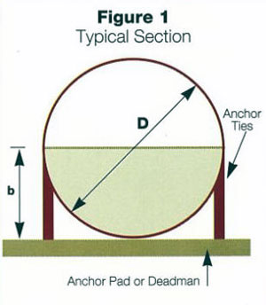
For pipes, whether they are concrete or metal, the computations to determine the point of flotation are slightly more difficult than for rectangular or square underground structures. The figure depicts a typical cross-section of a pipe anchored to a deadman. The value "b" represents the fill heights of flowable fill from the interior invert of the pipe upward. "D" is the known interior diameter of the pipe. The accompanying table provides buoyant forces in units of pounds per linear foot of pipe for various pipe diameters and depths of flowable fill. Linear interpolation can be performed for pipe sizes between those shown in the table. The upper right side of the table is "b" depths up to the midpoint of the pipe whereas the lower left side illustrates the depths of "b" from the pipe to invert to the crown of the pipe. The total weight of the pipe and any deadman anchors must be greater than the buoyancy force in the table.
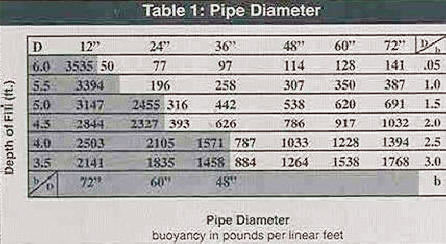
There are several items related to these calculations that should be kept in mind. Be sure to allow a margin of safety for each pour by keeping the depth of the pour below each indicated "b" value. Anchor ties and their embedments must be capable of resisting the maximum buoyant force that will be generated during the flowable fill pour. Check with the manufacturer of the tie hardware to ensure that a sufficient safety factor exists for the ties. Keep the unit weight of the flowable fill as low as possible, certainly below the unit weight of any deadman anchor concrete. The table is based on a unit weight of 125 pcf. The buoyancy force units in the table may be adjusted relative to flowable fills that have unit weights greater or lower.
With attention given to the question of buoyancy as well as the other conditions of using flowable fills for backfilling around pipes, the success and acceptance of flowable fill can be assured.